Terbaru 39+ Servo Motor Circuit Diagram

ELECTRONICS TRICKS AND TIPS How to make a Simple Servo Sumber electronicstrick.blogspot.com
Servo Motor Controller Circuit ElectroSchematics com
This is the simple basic design of servo motor controller with pulse generator It uses the CMOS IC 7555 in the Astable mode to generate pulses to drive the servo motor The circuit can be suitably modified to get pulses of sufficient length A Servo is a small device that has an output shaft

PLC and SCADA Servo Motor Sumber plc-technique.blogspot.com
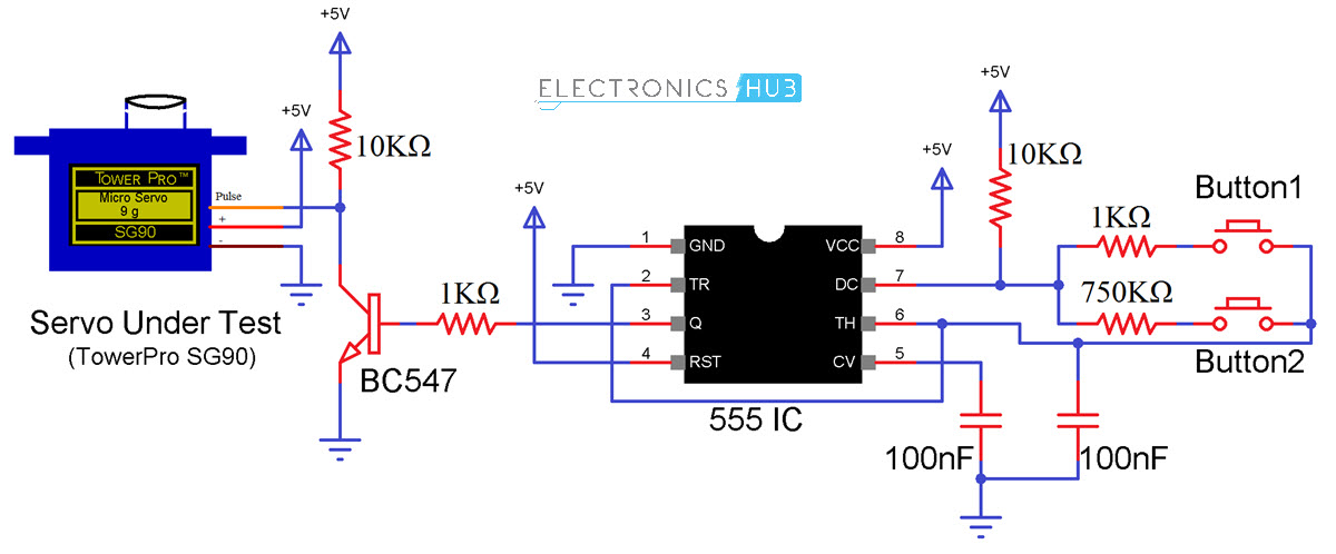
Servo Motor Tester Circuit Diagram using IC 555
21 05 2020 Servo Motor Tester Circuit electronics Servo Tester Circuit Diagram and Working Explanation A servo testing circuit is shown in the above schematic diagram Now as we discussed earlier for the servo shaft to move left all the away We have to give 1 18 turn on ratio and for the shaft to rotate all the way to the left we need to give PWM
Servo Motor Driver Circuit Sumber www.theorycircuit.com
Servo Motor Driver Circuit
07 12 2020 Here sub micro size servo motor is taken as a target device and we developed servo motor driver circuit for that motor Servo motors are widely used in different types of applications and suitable for movement or rotation based mechatronic needs Circuit Diagram Construction working Every servo motors will have three terminals one for
Zouhair electronics Lab 21 Servo motor control Sumber moroccoele.blogspot.com
Servo Motor Wiring Diagram Free Wiring Diagram
04 06 2020 Variety of servo motor wiring diagram A wiring diagram is a simplified conventional pictorial depiction of an electric circuit It shows the components of the circuit as streamlined forms and the power and signal connections in between the devices
DIY Servo Motor Cheap and with Plenty Muscle Bayesian Sumber bayesianadventures.wordpress.com
Servo Motor Control with an Arduino All About Circuits
You can connect small servo motors directly to an Arduino to control the shaft position very precisely Because servo motors use feedback to determine the position of the shaft you can control that position very precisely As a result s ervo motors are used to control the position of objects rotate objects move legs arms or hands of robots move sensors etc with high precision

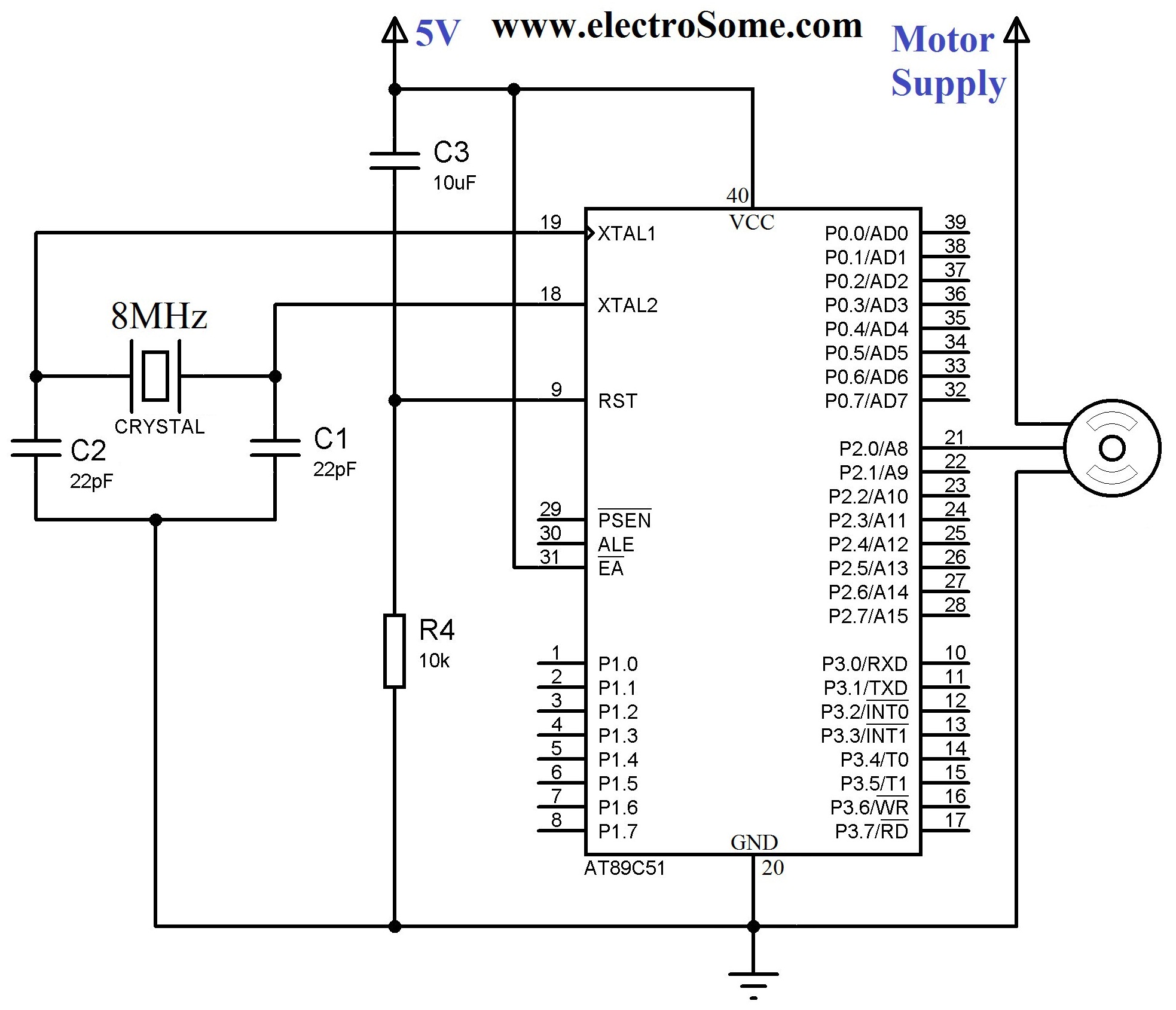
Interfacing Servo Motor with 8051 Microcontroller using Sumber electrosome.com
Servo controlling circuit
The output of the circuit goes to control input pin in servo motor servo motor ground goes to circuit ground and servo power input goes to suitable power source can be the same 5V as used to power this circuit The pinouts used on differnet servo motors vary but the wire colors are generally so that black is ground read is power and the

Stepper Motor Generator Xtreme Circuits Sumber xtremecircuits.blogspot.com
Servo Motor Components Circuit Diagram
Servo Motor v1 0 by Circuit Diagram Available in the web editor For instructions on how to use this in Circuit Diagram desktop see installing components

Kirk s Awesome Projects ECE Rocks Robotic Arm Gripper Sumber kirkmacaraegprojects.blogspot.com
Servo Motor Types and Working Principle
28 10 2020 The working principle of this servo motor is similar to the normal induction motor Again the controller must know the exact position of the rotor using encoder for precise speed and position control Working Principle of AC Servo Motor The schematic diagram of servo system for AC two phase induction motor is shown in the figure below
Index 3 Measuring and Test Circuit Circuit Diagram Sumber www.seekic.com
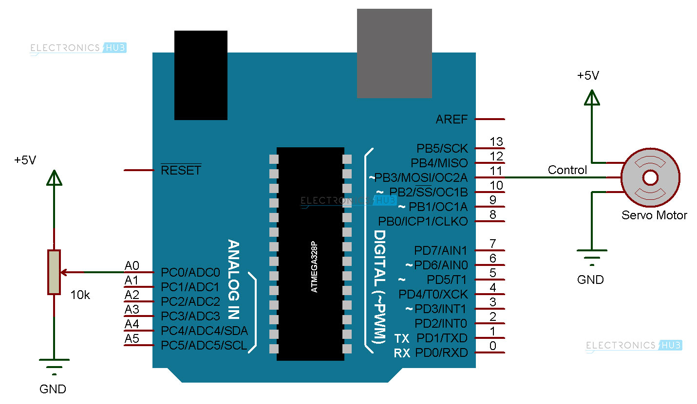
Arduino Servo Motor Control Tutorial with Circuit Diagram
15 08 2020 Arduino Servo Motor Circuit Diagram and Explanation In normal cases we need to go to the registers of controller for adjusting the frequency and for getting required duty ratio for accurate position control of servo in ARDUINO we don t have to do those things
Servo Motor Tester Circuit Diagram using IC 555 Sumber circuitdigest.com
Connecting a Servo Motor to An Arduino Microcontroller
Servo motors that don t produce high torque typically contain plastic gears A better look at the circuit board dc motor and potentiometer Arduino to Servo Motor Wiring Diagram To begin wire this circuit Most servo motors run on 5V so you can attach the red lead to the Arduino s 5V pin
Servo Motor Tester Circuit Diagram using IC 555 Sumber circuitdigest.com

Arduino Servo Motor Sumber www.electronicshub.org

DC Servo Motor Controller Circuit Diagram Sumber w3circuits.blogspot.com

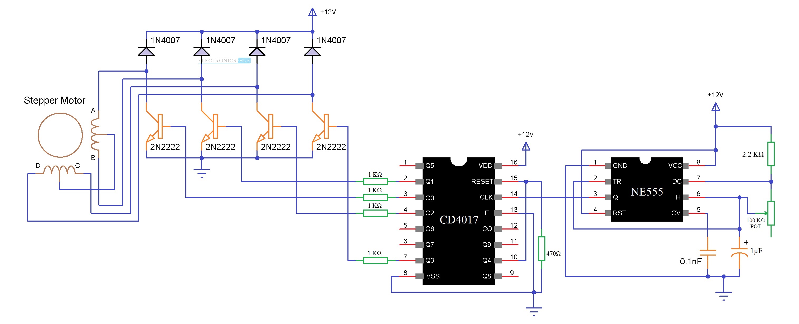
Stepping Motor Stepper motor controller circuit Sumber setppingmotor.blogspot.com

Stepper Motor Driver Circuit Sumber www.electronicshub.org


0 Komentar